 Copyright © Michael Richmond.
This work is licensed under a Creative Commons License.
Copyright © Michael Richmond.
This work is licensed under a Creative Commons License.
In the late 1800s, the refractor was King: the largest telescopes in the world were the 36-inch at Lick Observatory and the 40-inch at Yerkes.
But around the turn of the century, astronomers decided that they needed as much light-gathering power as possible in order to measure spectra and detect faint stars and galaxies on photographic plates. Reflectors could be made larger than refractors, so the tide turned, and mirrors with larger and larger diameters took over. George Ellery Hale was the driving force behind the construction of a series of very influential instruments:
For most of the twentieth century, refractors fell out of the mainstream of professional astronomical research.
But in the past 20 to 30 years, they have made a strong resurgence, as a result of three factors:
One of the cheapest and most efficient ways to find (and characterize) exoplanets is via the transit method. All it takes is the ability to measure the light from a star to a tenth of a percent or so (in other words, to the millimag level). But since there are so many stars in the sky, in order to find the rare transit events, one must measure thousands or tens of thousands of stars at a time. Which brings us to ...
| Mag | Approx. Number of stars |
| 5 | 2000 |
| 6 | 6000 |
| 7 | 18,000 |
| 8 | 52,000 |
| 9 | 190,000 |
| 10 | 450,000 |
| 11 | 1,300,000 |
             Q:  Where can one find these numbers?

             A:  Try the "Search" tab at  the Gaia Archive
In order to check them all for exoplanets -- or for other interesting properties -- it makes sense to use an instrument which has a wide field of view, so that you can measure hundreds or thousands of stars in a single image.
The same is true if one is searching for rare transient events, such as GRBs, SNe, or the optical counterparts to gravitational wave sources. Starting in the late 1980s, astronomers started to combine wide-field telescopes, electronic cameras, and computer-controlled motors in order to carry out surveys of large sections of the sky in an automated manner. I enjoyed dabbling in the early days of automating telescopes myself ...
A connection between football and astronomy?

Sports Illustrated cover for Jan 24, 2011
Yes! Photographers who cover sports need lenses with two key properties:
Well, these are exactly the same major concerns of astronomers. But since there are many more professional sports photographers than astronomers, and since their newspapers and magazines and websites will pay them well to get good pictures, some of the major lens makers have created lenses which meet these needs and are not too expensive. This article might give you some idea for the lenses commericially available.
Q: What are the typical prices for these lenses?
Let's go through one example to see how this works. We begin with a lens, of diameter D and focal length L.
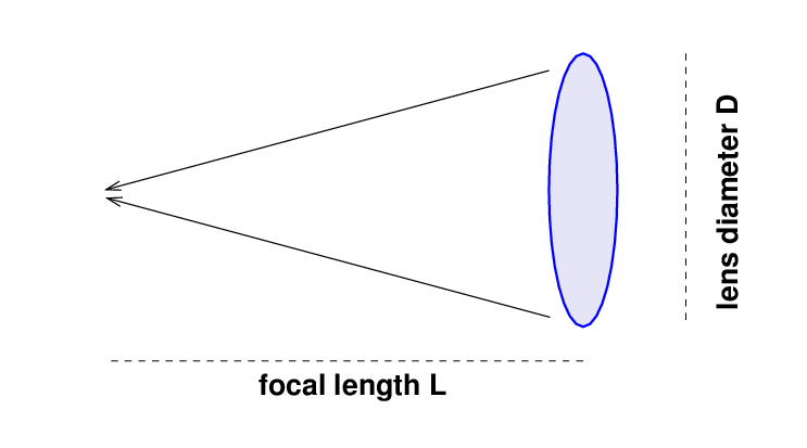
The focal ratio of the lens is
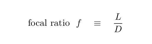
On the other end of the camera is a detector with pixels.
![]()
The relationship between a pixel's physical size p and its angular size α on the image plane is simply
Now, some typical numbers for astronomical instruments of interest, as you will see eventually, are
That might sound like a small telescope, but it's a pretty darn big lens.
One can use this information to compute the angle subtended by pixels in a telescope, and the solid angle covered by each pixel.
   Lens Diam D   focal ratio   focal length   pix ang size   pix ang area
     (mm)           f              L (mm)        (arcsec)     (sq. arcsec)
 ----------------------------------------------------------------------------

    100            2.5            250             8.25           68.07

    100            5              500             4.12           17.02

    100           10             1000             2.06            4.25

    100           15             1500             1.38            1.89

 ----------------------------------------------------------------------------
So, in general,
Q: Which is better: a short focal length, or a long focal length?
Well, the only real answer is "It depends on what you are trying to do." For example, suppose you are trying to make the best measurements possible of the BRIGHTNESS of some stars. We'll discuss this in a future lecture, but one way to compute the signal-to-noise ratio in the measurement of a star with an electronic detector looks like this:
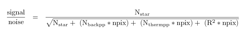
where
     N(star)                 is the number of electrons from the star
                                   which fall within the aperture

     N(backpp)               is the number of electrons Per Pixel
                                   due to the sky background

     N(thermpp)              is the number of electrons Per Pixel
                                   due to thermal effects

     R                       is the readout noise per pixel, in electrons

     npix                    is the number of pixels in the aperture
In certain situations, the limiting factor in the measurements becomes the noise due to background or thermal effects in the detector. In such cases, spreading the light from a star over a large number of pixels will lead to a larger amount of noise.
So, in SOME situations, a larger focal ratio, and longer focal length, creates much smaller pixels, spreading out the light from an object over many pixels. If we are fighting against sources of noise -- such as background light or readout noise or dark current -- which affect each pixel independently, then we will lose the signal-to-noise battle as the light of our target is spread out over many pixels.
In other words, a short focal ratio means big pixels, and, in SOME situations, big pixels mean a higher signal-to-noise ratio in short exposures.
  Q:  What happens if we make the focal ratio _too_ small,
           and the pixels get _too_ big?
Yes, if the pixels are so large that they cause neighboring stars to blend together, we won't be able to measure the light of each star properly.
In an ideal case, astronomers who want to detect and measure one particular type of celestial object can design a set of lenses and detectors which provide the best signal-to-noise ratio for their project.
One ambitious project uses a LOT of small refracting telescopes to take pictures of (almost) the entire sky, all at once. The first phase of this project was based on Evryscope:
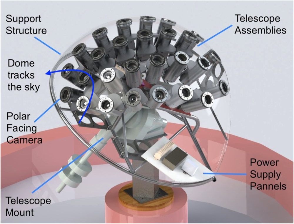
Figure 2 taken from
Ratzloff, J. K., et al., PASP 131, 075001 (2019)
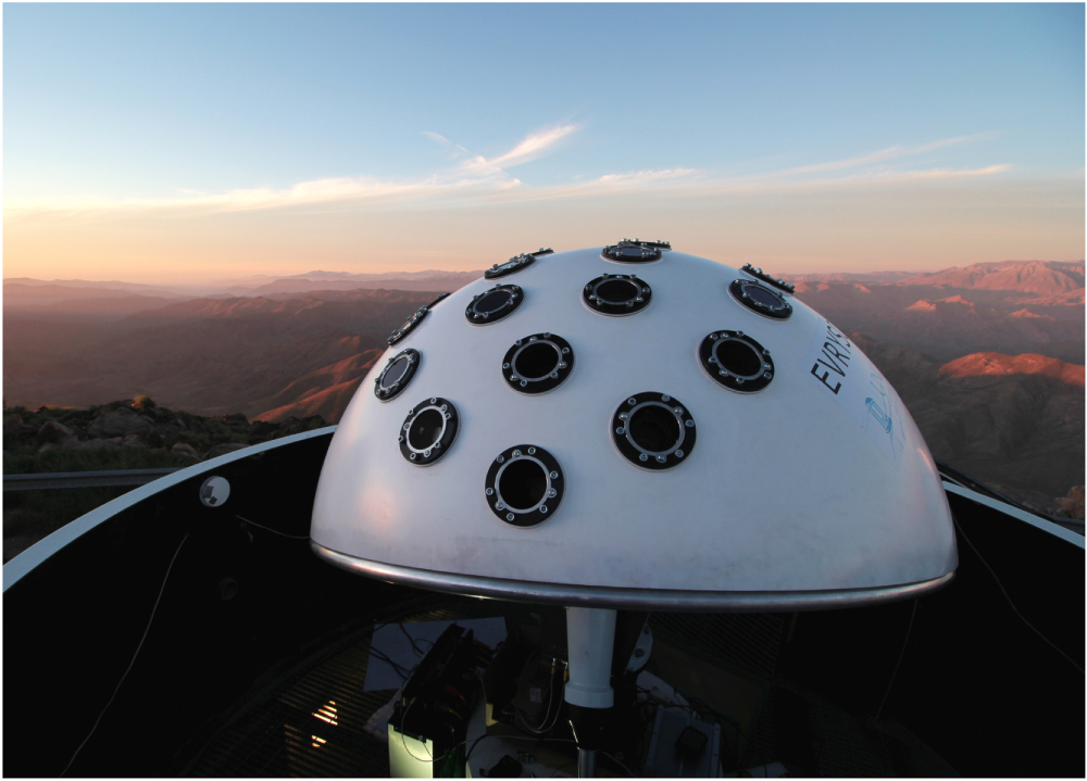
Figure 1 taken from
Ratzloff, J. K., et al., PASP 131, 075001 (2019)
One attractive feature of the device is its relatively low cost. For example, the optics are all available off-the-shelf.
  Q:  How much does each of the Evryscope's camera lenses cost?
          (look for Canon 85 mm f/1.4)


  Q:  How many lenses does the Evryscope have?


  Q:  What's the total "optics" cost?
The main science goal is to detect relatively bright transient and variable objects. The key here is to cover a LARGE AREA on the sky. The scientists running Evryscope recently published a paper describing the results of one small region of the southern sky, after only about 8 months of observations:
The scientists who built Evryscope have now moved to a larger, more sophisticated instrument: ARGUS.
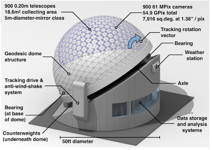
Figure 1 taken from
Law, N. M., et al., PASP, 134, 035003 (2022)
This combination of telescopes and detectors will be able to reach much fainter stars. By coadding images over the course of a night, Argus may be able to measure stars of magnitude 24!
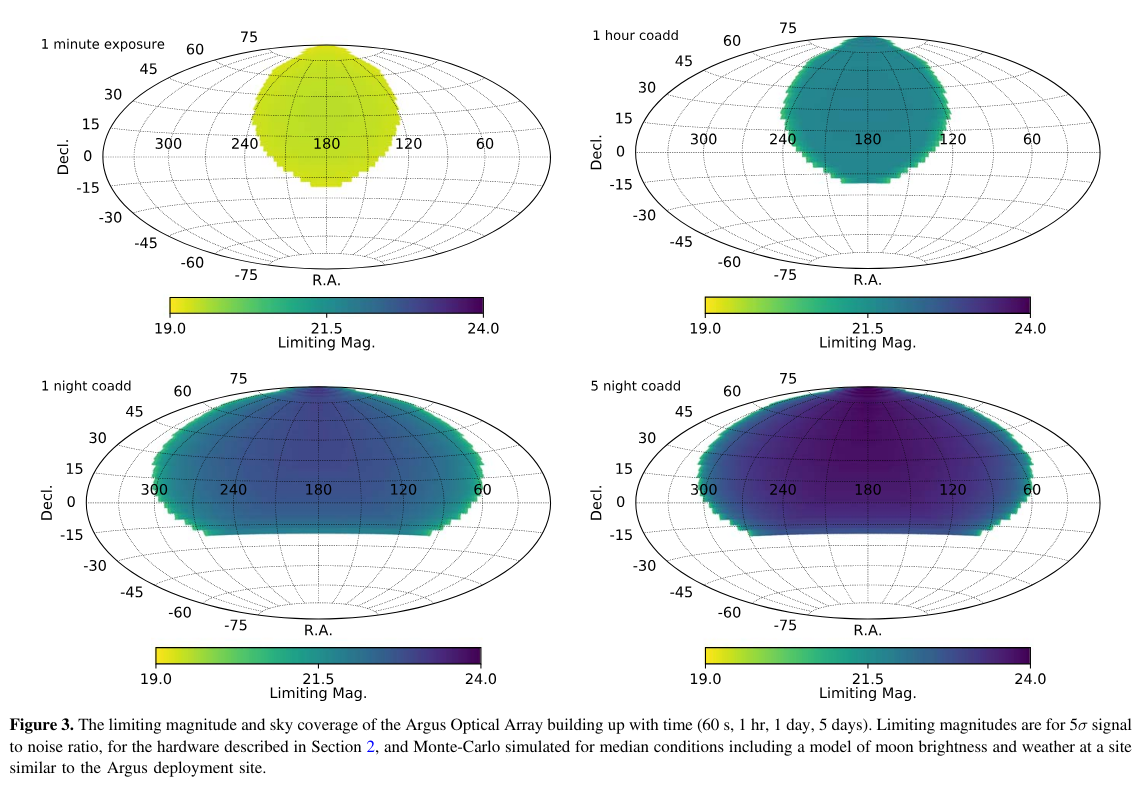
Figure 3 taken from
Law, N. M., et al., PASP, 134, 035003 (2022)
Another new refractor-based instrument has a different goal: detecting low-surface brightness galaxies. These are galaxies in which the starlight is spread out over a large area on the sky, which makes them blend into the background sky brightness.
For example, consider this region near the big, bright, spiral galaxy M101. The crosshairs are at location
RA = 14:03:49.4 Dec = +53:59:20
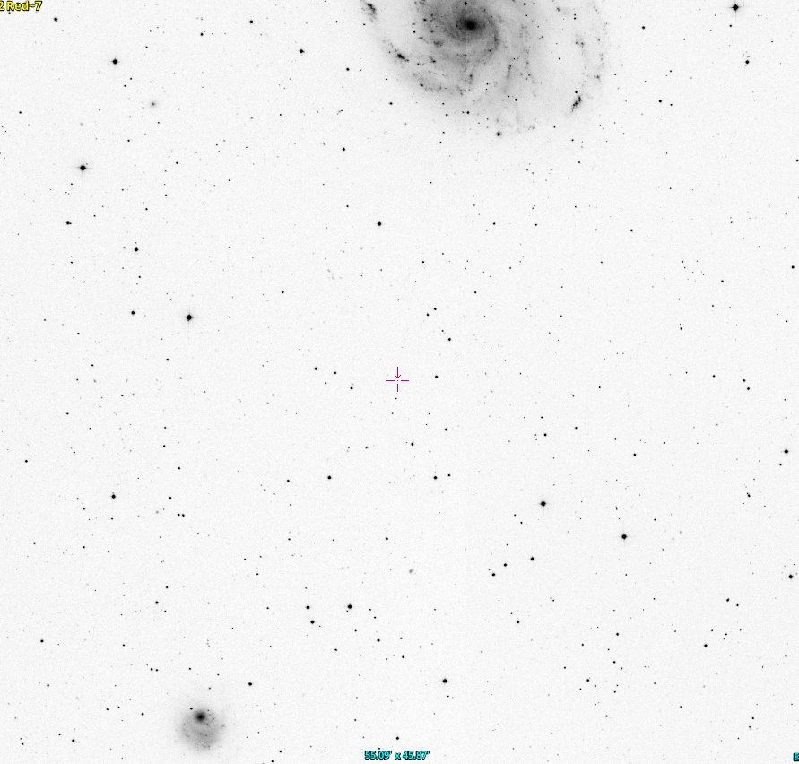
Do you see a galaxy somewhere NEAR the crosshairs?
Perhaps you could use AladinLite to look for it.
Here, I'll help. This is the same region of the sky, but with the contrast increased. I'll also circle a star which has roughly the same magnitude as the galaxy we are seeking.
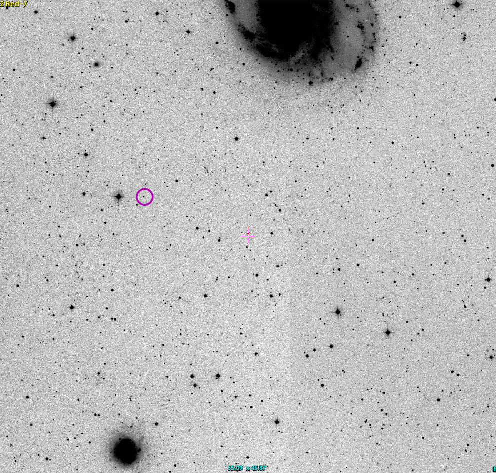
Do you see it now?
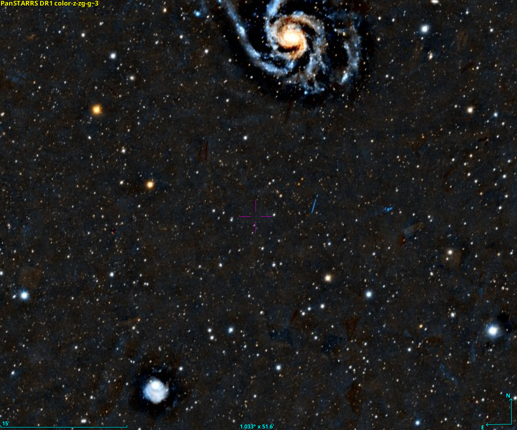
Here, let's try a color composite from the Pan-STARRS survey. Does this help?
Well, if you can't find it, here's a chart from the paper The Dragonfly Nearby Galaxies Survey. III. The Luminosity Function of the M101 Group. Note the box labelled "DF1" near the center of the figure, just below the big galaxy M101. There's a zoomed-in closeup at the bottom.
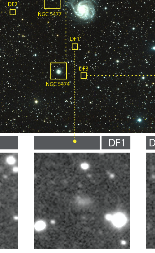
Taken from Figure 6 of
Danieli, S., et al., ApJ 837, 136 (2017)
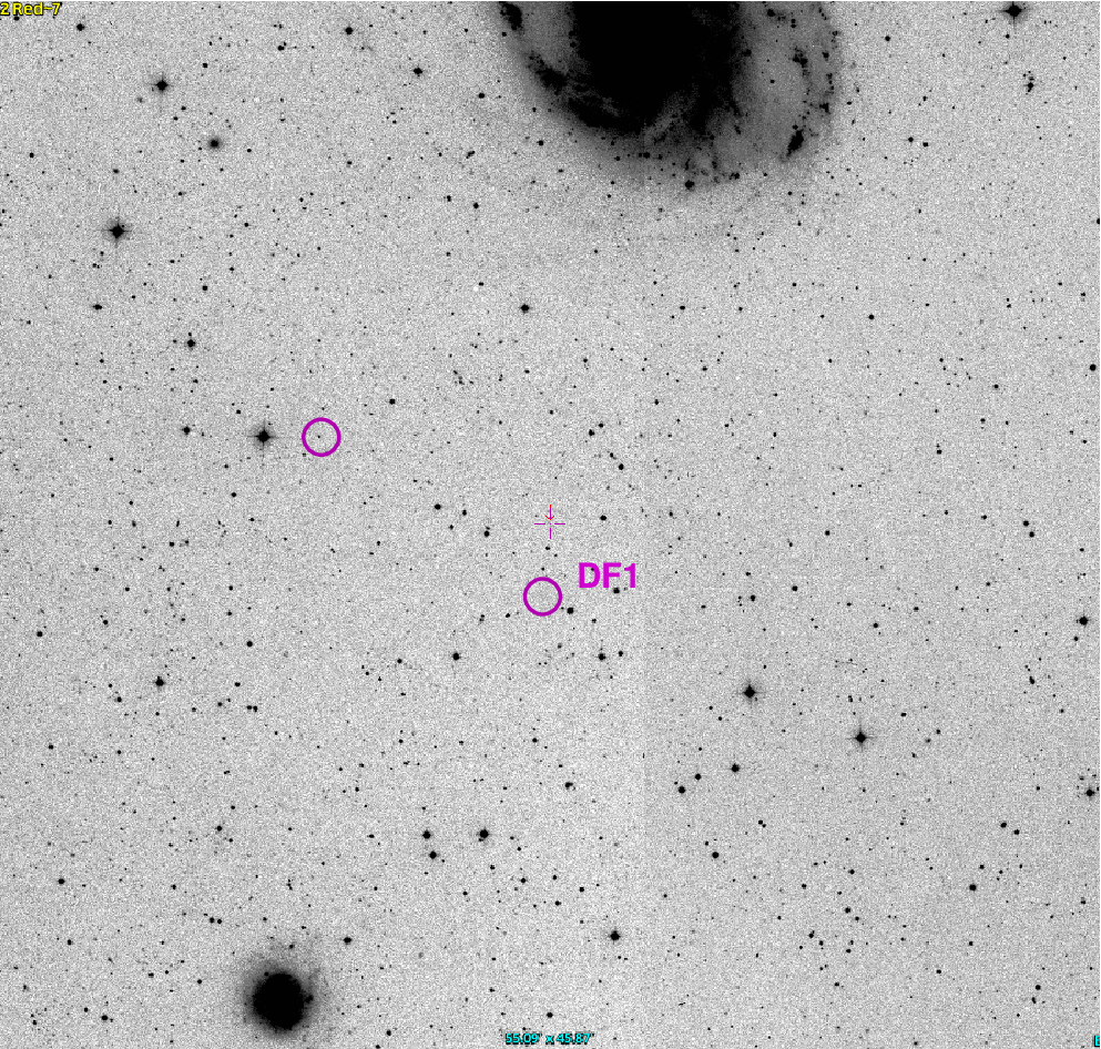
Here it is in the original DSS image:
The challenge of detecting these objects with very low surface brightness is to separate their light from that of the background. It turns out that using relatively large pixels helps: the fewer pixels over which a galaxy's light is spread, the smaller the contribution from readout noise and dark current. One must also perform very, very careful image reduction and calibration.
The Dragonfly Array was designed to combine the images taken by 10 telephoto camera lenses, all staring at the same region of the sky.
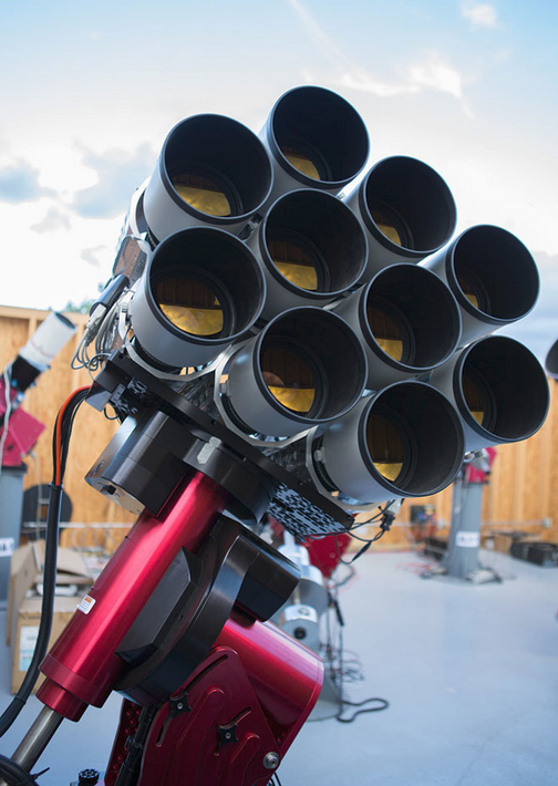
Image courtesy of the
Dragonfly Telescope gallery
A later upgrade increased the number of lenses:
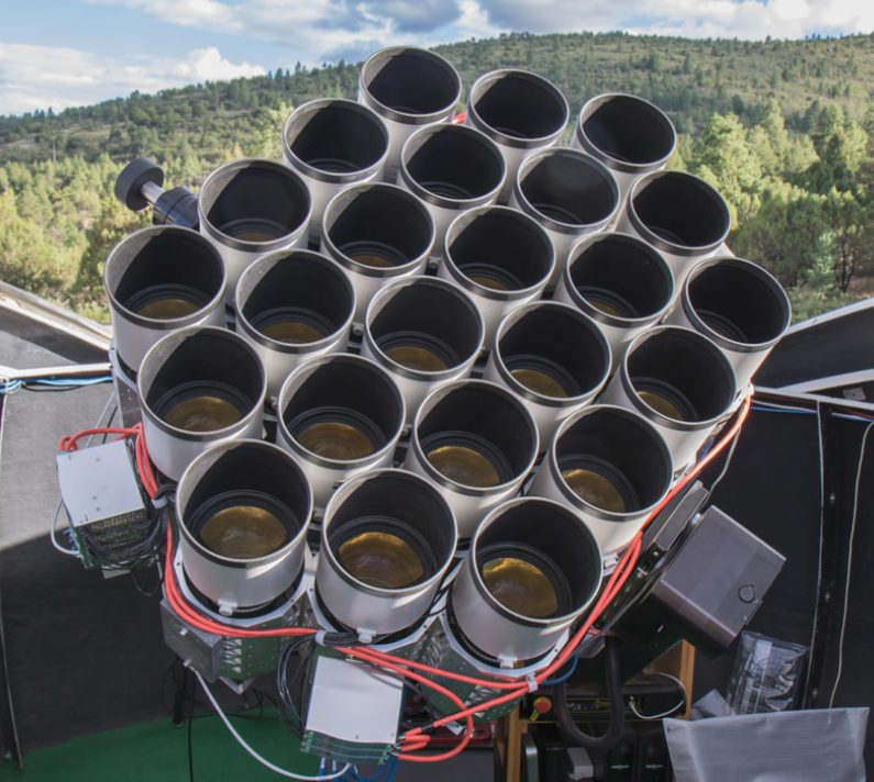
Image courtesy of the
Dragonfly Telescope gallery
This instrument has been so successful at finding low-surface-brightness galaxies that its builders at the University of Toronto and Yale have decided to help it morph into MOTHRA!
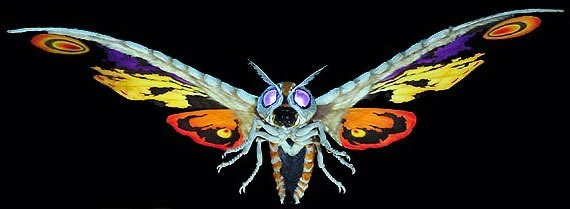
Whoops, sorry. Wrong Mothra. This is just PART of the new instrument -- one of 30 fork-mounted components.
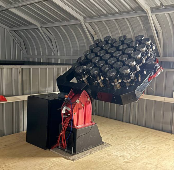
Image courtesy of
Dragonfly Telescope website
Though the instrument is still under construction, it promises to be a ... significant upgrade in complexity and capabilities:
Dragonfly is evolving into the Modular Optical Telephoto Hyperspectral Robotic Array (MOTHRA), with 1140 telephoto lenses spread over 30 large fork mounts at the Obstech observatory in Chile. The upgraded array will be equipped with ultra narrow-band tilted interference filters, a technology pioneered by the Dragonfly Spectral Line Mapper. Upon completion, MOTHRA will be the equivalent of a 4.7m aperture f/0.07 refractor with an R=800 integral field spectrometer and a 9 square degree field of view.
Copyright © Michael Richmond.
This work is licensed under a Creative Commons License.